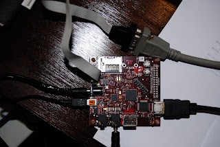
After spending some time to collect documents of all on-board devices, what is found is the exciting multimedia capability of the MPU and, especially, the IVA2.2 subsystem. IVA is the acronym of Image, Video, and Audio subsystem. It is especially amazing that the SGX module equips an universal shader engine which enables the capability to service not only the MS shader model 3 (VS and PS; GS is not mentioned in the spec so has to be invetigated in advance) and OpenGL2.0 fragment shading language (GLSL), but also, supposely, the programmable video codec engine. Universal shader engine is the trend of GPU design in 2 years ago when I'm still a Direct3D driver engineer.
Following list highlights the important features of the MPU and IVA2.2 subsystems ...1. MPU subsystem modules
- ARM subchip
Cortex-A8 core (r1p1)
ARMv7 ISA (Thumb-2, Jazelle RCT)
NEON SIMD coprocessor (VFP lite, media streaming)
16K I/D L1 cache (4 way set associative, 64 bytes cache line), 256K L2
- INTC (96 synchronous int lines)
- Asynchronous interface with core logic (this probably refers to the AXI interface)
- ICE-Crusher, ETM, ETB modules
2. IVA subsystem features (image/video/audio)
- IVA2.2, based on TMS320DMC64x+ VLIW DSP
- 32-bit fixed point
- VLIW
* 6 ALU
* 8 instructions per cycle, 8 execution units
8x8 MAC (multiply accumulate)
6x6 MAC
((a+b+c) >> 1) interpolation
two 32x32 multiply per cycle
- dynamically mixed 16/32 bit instruction sets
- 32K P(direct-mapped)/D(2-way-set 4bytes cache line) L1 cache, 48K SRAM
64K(2-way-set 128bytes cache line) L2, 32K SRAM, 16K ROM
- private DMAC
128 channel, 1D/2D addressing, 64-bit read x2 and write x2 ports, 32/64 bytes burst
- L1 INTC
- 32 entry MMU
3. PowerVR SGX
- hw 2D operations: vector graphics, BLTs, ROPs
- universal shader engine (MS VS/PS3.0, OGL 2.0)
- geometry dma
- virtualized memory addressing
- programmable video codec support: H264, H263, MPEG4, WMV9, JPEG
- 2048 x 2048 x 24bpp resolution
- 256 24-bit palette entries
- picture-in-picture(overlay), color-space conversion, rotation
- remote frame buffer support
- LCD pixel/bus interfaces (MIPI DPI/DBI 1.0)
- NTSC/PAL CVBS & S-video analog output
4. Four DMA controllers in the system
- sDMA (system DMA)
* one read and write ports
* 32 channels (prioritized)
* 96 hw-reqs
* 256 x 32 FIFO
- EDMA (enhanced DMA)
for IVA2.2 subsystem
- Display DMA
- USB HS DMA
As a novice user of a new development board, the first few things to clarify is the system power and clock distribution and the memory space mapping. Let's forget the former temporarily which is usually just a tedious spec reading, and start with the relatively "interesting" topic: the mapping of the memory space.
According to the TI application processor technical reference manual (spruf98b), the system memory space has two level of partition granularity in the 4G space:
- Level 1 - 4 quaters (Q1, Q2, Q3, Q4), each corresponds to a 1G address space
Q0 (0x00000000 ~ 0x3fffffff)
boot space (1M)
GPMC (1G)
Q1 (0x40000000 ~ 0x7fffffff)
on-chip memory (128M)
boot-rom, SRAM
L4 interconnects (128M)
L4-core (16M), L4-wakeup (256K), L4-peripherals (1M)
L4-emu (64M)
L3 interconnect (128M)
L3-control regs, SMS regs, SDRC regs, GPMC regs (16M each)
SGX (64M)
IVA2.2 (64M)
SDRC-SMS virtual address space (256M)
Q2 (0x80000000 ~ 0xbfffffff)
SDRC cs0 (512M)
SDRC cs1 (512M)
Q3 (0xc0000000 ~ 0xffffffff)
SDRC-SMS virtual address space (512M)
- Level 2 - 8 blocks, 12M each, mapped to target spaces, where target spaces includes:
* Boot Space
1M in GPMC(Q0) or (according to sys_boot5 pin configuration) ...
On-chip ROM(0x40000000~0x400fffff) space
* GPMC Space
1G Q0
8 chip selects
gpmc_ncs0 to gpmc_ncs7
16M ~ 128M each block
programmable base and size
* SDRC space
1G Q2
2 chip selects
sdrc_ncs0 and sdrc_ncs1
64M ~ 512M each block
fixed base (0x80000000), programmable size for sdrc_ncs0
programmable base (default 0xA0000000) and size for sdrc_ncs1
* VRFB / SDRC-SMS (access to SDRC space through the rotation engine)
256M Q1
512M Q3
So now we have an initial view of system bus setup and the deployment of
subsystems and devices in the memory space. Are these listed features excites
you either? Let's examine them one by one in the upcoming study plans.


